We've updated the main website with the FTC flights report from last Sunday. Included is a short video of the highlights from the day.
http://www.AirCommandRockets.com/day71.htm
In putting together the pictures and video for the update we noticed that in both of the last two higher pressure flights the rocket was bending quite a bit on take off. This probably explains the lower than expected altitude. The rocket is very flexible and under the acceleration loading it just bends. This is likely to be inducing fairly large drag.
_______________________________________________

Friday, December 26, 2008
Monday, December 22, 2008
T8 FTC rocket flights
We had perfect launch weather this weekend, but since it wasn't a NSWRA launch day, we went back to our old launch site to test fly the FTC rocket and check out all its systems.
 We had to launch at a lower pressure in order to keep the rocket in the park. We launched the FTC rocket 4 times and also launched a number of other rockets on the day. There were no crashes on the day so we were happy.

We are putting together another update for our main website with more pictures and a video of highlights from the day. This should be available in the next few days, but it may be after Christmas depending on how we go for time.
____________________________________________________
 We had to launch at a lower pressure in order to keep the rocket in the park. We launched the FTC rocket 4 times and also launched a number of other rockets on the day. There were no crashes on the day so we were happy.
We are putting together another update for our main website with more pictures and a video of highlights from the day. This should be available in the next few days, but it may be after Christmas depending on how we go for time.
____________________________________________________
Thursday, December 18, 2008
Still Here
In the lead up to Christmas we've had to curtail rocket development as we are busy with family and work related obligations. Development is still continuing in the background although not enough for an entire update. I am waiting until the start of the holidays to have more time for development. We will also be extending the workshop under the house to have more room for building and storing larger rockets.
Since the NSWRA picnic was also canceled due to bad weather we haven't had a chance to launch our FTC rocket yet. We will try to launch it on a weekend at the local park at a lower pressure to check out all systems. If all goes well, we will launch it at full pressure at the next NSWRA launch day.
We hope everyone has a great Christmas and a safe new year!
____________________________________________
Wednesday, December 03, 2008
Software
We've been spending quite a bit of time this week writing and testing the FC V1.6 software. We are making it a little more user friendly to set up and operate in the field. The delay, offset and multiplier parameters were more difficult to set because you really needed to have the manual with you. Although you loose the precision of V1.5 the new settings allow you to set the time directly, so you can quite easily set it in the field. The settings allowed, however, should cover pretty much most flight profiles.
This also has meant that we've needed to update the operator manual which will be published when the FC is finished.
Last weekend was supposed to be a launch day but the wet weather cancelled those plans. :( NSWRA is meeting again this weekend so we will try to make it, but at this stage I'm not sure since family commitments were scheduled around last launch day and can't be moved. In any case NSWRA is meeting again the following week for a launch/picnic day, so we should be able to make it to that. We have four rockets itching to get off the pad, so they'll need to wait a bit longer.
____________________________________________________________
Wednesday, November 26, 2008
Open Day, G-switch, Acceleron V
We've update our main website with the latest development progress on a number of fronts.
http://www.AirCommandRockets.com/day70.htm
 I've spent most of last night doing final work on the FTC rocket to get everything well secured. The rocket has also had another pressure test to 180 psi without any visible issues. Phil had a good suggestion to re-string the nosecone so that the parachute is attached to the nosecone and the nosecone is attached to the rocket. In this way more tangles can be avoided. I've also been a bit concerned at the forced on the top of the rocket where the parachute is attached. The main worry is that a high speed deploy could separate the payload section from the rest of the rocket. I've now threaded another kevlar line through the full length of the payload bay that is attached firmly to the pressure chamber end cap and the other end is looped through the main parachute line. Should the parachute rip off the payload bay, it should all remain connected to the rocket.
We are hoping for nice weather this weekend so we can go flying.
____________________________________________
Friday, November 21, 2008
Open Day Preparation
We've been flat out this week trying to get things ready for the open day this Saturday. The main project has been a rebuild of the Acceleron booster. This is our biggest booster to date at ~33L capacity. Acceleron III was 24L and Acceleron IV was 18L because it used 1.25L bottles.
The new booster has three 2L bottle spliced pairs tornado coupled together per segment. There are three segments in total. At 130psi the pyro rocket equivalent is an H310. (~250Ns total impulse)
We have simplified the pod at the top of the booster. The deploy mechanism is the same as the previous versions of Acceleron based on a FC, pressure switch and servo, but the parachute is no longer located in the pod. This meant that the pod could be smaller and lighter. The parachute now resides between the bottle necks of one segment so there is no extra drag. The parachute will be deployed using the piano hinge technique we have been using recently. This should mean the parachute opens sooner. Too many times before the parachute deployed late.
_________________________________________
Tuesday, November 18, 2008
Batteries and FC V1.6 progress
Batteries
I'm always on the look out for small yet moderately powerful batteries to power the on board electronics. It's always a compromise between cost, weight, voltage and current capacity. I've been using the Lithium CR123As in pairs to give me 6V but the amount of current they supply is much more than I need and hence are unnecessarily large. 9V batteries are pretty good in price, voltage and current but are comparatively heavy ~45 grams. A stack of button cells generally cannot supply enough current to drive servo motors.
When cost isn't an issue and you are after minimal weight and maximum power density then I expect some of the tiny Li-po batteries are the way to go. But they do need a charger, are expensive and not readily available.
I came across this video a few weeks back, and finally had a go at pulling apart a 9V battery this week.
http://au.youtube.com/watch?v=tr5ZB1eFhwc
Judging by the YouTube video comments a number of issues need to be looked out for:
- Only go for Energizer or Duracell alkaline batteries
- Don't short anything out while doing so.
- Wear gloves should you spill some acid
I only need 6V to power all the electronics so 4 of the cells are all I need. It also means that getting two 9V batteries I can make up three 6V battery packs. At only a few dollars per battery pack it means they are very affordable, and available everywhere. After removing the casing, connectors, and two cells the weight of the battery drops from 45 grams to 25 grams. In comparison a AAA 6V battery pack weighs ~44 grams, and AA battery pack weighs ~90 grams.
I just soldered wires to the contacts to make up the connections. I have started doing this ever since we found that some battery holders under G forces can easily loose contact. They powered the flight computer and servos just fine.
The small form factor means that they can be rearranged to fit the available space.
Flight Computer V1.6
I've ordered all the parts now for the next iteration of the flight computer. This will be a slightly larger run of 20 compared to the 10 made for V1.5. I am waiting for all the components to arrive first in order to verify their dimensions before finalising the PCB. I'm also investigating a small and cheap G-switch option to trigger it rather than the commercial G-switch costing around $9. The PCB will be designed so both variants can be used.
The updated software is also almost finished. We had a request come in from a water rocket team (Oberon WR) who built version 1.5 of the FC but their servo was only turning only around 90 degrees even though the full range of movement was 180 degrees. We tested this with one of our cheap 180 degree servos and sure enough the full range was around 90 degrees. I checked the PWM signal on the CRO and the standard range of ~1ms to ~2ms was correct coming out of the FC. I updated the code to give a range between 0.5ms and 2.5ms and that gave the full range of the servo movement. If I have sent you a copy of the V1.5 code, I can send you the update if you have this issue. Other servos worked fine with the 1-2ms timing.
It seems that some servo manufacturers don't adhere to the standard 1-2ms for full range. This change will also be rolled into V1.6. It may end up as another configurable parameter: 1-2ms for full range or 0.5 - 2.5ms for full range.
________________________________________________
Sunday, November 09, 2008
FTC Parachute Deployment Mechanism
We've posted an update on our main website with details of how the T-8 FTC parachute deployment mechanism works.
http://www.AirCommandRockets.com/day69.htm

Included in the update are photos and a short video of how the mechanism works. We are hoping to test fly it at the next opportunity.
_______________________________________________________
http://www.AirCommandRockets.com/day69.htm

Included in the update are photos and a short video of how the mechanism works. We are hoping to test fly it at the next opportunity.
_______________________________________________________
Wednesday, November 05, 2008
Sewing on fins
We decided to sew the fins to the FTC rocket. Hopefully this will provide additional strength for the expected G forces. Okay so it's not your ordinary needle and thread but the idea is the same. The wire threads through the split sleeve and through the fin. The wire does not go through the pressure chamber.

PL premium still provides the majority of the strength, but the wire is there to ensure the fin does not come off should the glue fail while the rocket stretches during pressurisation. The wire also keeps the fin in place while the glue dries.
Once the initial glue dries the wire is trimmed and the twisted part is folded down and a more glue is used to create a fillet on either side of the fin. We are trying a technique to minimise the amount of bubbling from the PL, as PL is not very nice for smooth fillets. After we form the smooth fillet with the PL we place scotch tape over the fillet to minimise the amount of atmospheric moisture entering the glue. Hopefully this will slow down the cure rate and won't produce the big bubbles we normally get. Will have to check tomorrow to see how it went.
__________________________________________
Monday, November 03, 2008
NSWRA Open Day
NSWRA is having an open day this month on the 22nd November at Toongabbie East Primary School. We will have a water rocket stand there along with the pyro guys. If you are interested in any form of rocketry why not come along? See the flyer below for details:
We are going to be busy over the next few weeks to get the rockets ready for the open day. We want to bring the Polaron rocket with the drop away boosters, the new bigger Acceleron booster, and the new FTC rocket with us. We'll also bring along some of the other smaller rockets.
We have had a bit of a break from water rocket development this last month due to other family commitments, but are now back and should be updating the main site and blog more frequently.
I've also been continuing work on the next iteration of the flight computer (V1.6). The software has had a bit of a revamp to make it easier for the rocketeer. I'm also in the process of laying out a new smaller double sided PCB for it. We've located a local PCB manufacturer with very reasonable rates for the boards so we will likely have around 20 of them made, most of which will go up for sale assembled as was with V1.5. I've switched from using an old version of Protel for the schematic and PCB layout to Eagle which is much more advanced and certainly has some very neat features. Luckily the PCB manufacturer can take the Eagle files directly which greatly simplifies the process.
______________________________________________________________
Wednesday, October 22, 2008
FTC Payload
I've been quite busy this last week with non-rocket related things but have continued the steady progress on the FTC payload section in my spare time.
 All the components are now fitted inside the payload section, but more work is still needed to secure things a bit better for the expected G forces of around 70G. The entire payload section shown above currently weighs 118 grams and includes the complete deployment system with servo motor, parachute, flight computer, altimeter and batteries. The flight computer is V1.5 on a 25mm wide PCB to fit into the T-8 tube.
The complete deployment system is only made from items found around the house. The full details will be given in the next main website update along with a video of how it works.
We will be picking up some kevlar line for the parachute on Saturday which should make things a little lighter and stronger.
It's been fun trying to fit everything into such a small space. For deploying the same size parachute as we have been using on our smaller rockets the entire deployment system is about 25% lighter than our existing ones and has a lot less drag.
____________________________________________________
Tuesday, October 14, 2008
FTC rocket update
Over the past couple of days we have been putting a bit of effort into getting the FTC rocket ready for its first flight. I did a test to see if the fins can be glued directly to the reinforced FTC body, but PL premium does not hold well to the the glass strapping tape. They will have to be attached a different way.
The parachute ejection system is not complete yet, but is working quite well. We can use a fairly large parachute in it.
I've started soldering together V1.5 of the flight computer in a format that fits into a T8 tube. There will be one small RC servo motor for deployment. The payload section will also include one of the altimeters. Other than that, the pressure chamber is finished.
Pictures will be posted when more of it is assembled.
________________________________________________________
Thursday, October 09, 2008
Thrust Data Available
We have spent all week collating the data from the thrust tests. Our main website has now been updated with the results here:
http://www.AirCommandRockets.com/day68.htm
There were some interesting results and we want to do further follow up experiments, as well as some new ones.

It's a bit of a long write up so feel free to skip the boring sections.
_________________________________________________________
http://www.AirCommandRockets.com/day68.htm
There were some interesting results and we want to do further follow up experiments, as well as some new ones.

It's a bit of a long write up so feel free to skip the boring sections.
_________________________________________________________
Saturday, October 04, 2008
17 Tests in 3.5 hours
Today was a good day for testing. We went through quite a bit of air out of the scuba tanks, but the tests went relatively quickly and we got through most of what we wanted to get done.

We are in the process of analyzing the results at the moment and putting together a video of the tests as well. It will take a few days to write up the results.
Some of the tests included:
FTC Rocket
We have also done some more work on our FTC rocket. We have the fins cut out now, but more importantly come up with the way we want to do parachute deployment in a T-8 FTC tube where there isn't a whole lot of room. The best part is that all the components are common items that can be found around the house.
_______________________________________________________

We are in the process of analyzing the results at the moment and putting together a video of the tests as well. It will take a few days to write up the results.
Some of the tests included:
- Robinson coupling choking and blow through effect,
- Jet foaming techinque with and without foam,
- Reduced mixing chamber for jet foaming,
- Some tests were done with a 9mm nozzle and some with a 7mm nozzle,
- Foaming agent concentration difference
- We tested 2L of carbonated drink in the rocket,
FTC Rocket
We have also done some more work on our FTC rocket. We have the fins cut out now, but more importantly come up with the way we want to do parachute deployment in a T-8 FTC tube where there isn't a whole lot of room. The best part is that all the components are common items that can be found around the house.
_______________________________________________________
Thursday, October 02, 2008
Software
After importing a lot of thrust data from the test stand into Excel it quickly became obvious that the data still needed a lot of processing before it was useful. While it is easy to do in Excel, it is quite tedious, as the data has to be trimmed, aligned in time, averaged, calibration scaling applied, total impulse calculated and then graphed. This was taking perhaps 10 minutes per data set so I decided to extend the functionality of the WDQ to CSV exporter application I wrote a few weeks ago.

The application now can do all of the above tasks. With a few mouse clicks I can get total impulse, average thrust, thrust duration etc. This allows us to quickly review the data during testing and alter our tests based on the observed data. This should help in the design process as we make changes to the design we can get instant feedback on the design.
The full software functionality will be covered in the day68 update with the calibrated test results.
We are hoping to do a full set of tests this long weekend.
______________________________________________
Monday, September 29, 2008
Calibrated Testing
This weekend we performed a number of calibrated tests on the test stand. We first measured the load cell's linear response by suspending successively heavier weights on the load cell, and then flipping the test stand over and applying the same weights again so that force was applied in the other direction. The load cell responded very well.
The first test was an attempt to measure the power loss due to the blow through effect in a rocket with Robinson couplings. The test results from the three identical firings were very good as the thrust curves were in very close agreement with each other. That gives us confidence on the repeatability of the experiments.
When we were testing the rocket without the couplings we had a small problem where the thrust curve just exceeded the gain setting and as a result the top of the curve was clipped. We will re-run this again but with a lower gain setting. We try to keep the gain as high as possible in order to get maximum resolution.
Full details of the tests and data analysis will be put on the main site in due time. We will rerun the non-coupling tests before publishing the results.
There were a couple of minor issues we had to resolve with the test stand initially such as the little locking tabs in the gardena release mechanism flying out during release. But once fixed the tests were quite quick.
Because we had the test stand and equipment setup on Saturday we didn't go launching any water rocket with NSWRA, although I went over with the kids to watch other people's pyro rockets. It was nice for a change not to have to go and spend a couple of hours setting and packing up, and I got to enjoy other people's rockets and actually had time to talk to them. I've put together a highlights video from the day up to about lunch time here:
http://au.youtube.com/watch?v=4PPcZH3pK0Q
_________________________________________________________
Sunday, September 21, 2008
Test Stand Details
We've put the details of the test stand on our main website here:
http://www.AirCommandRockets.com/day67.htm
It includes a couple of thrust curves.
_________________________________________
http://www.AirCommandRockets.com/day67.htm
It includes a couple of thrust curves.
_________________________________________
Friday, September 19, 2008
Test Stand First Firing
We ran our first couple of thrust tests on the new test stand. The tests were uncalibrated as we wanted to see what the overall performance was and if the gain on the amplifier is set correctly for the range of thrusts we will start testing with. Overall everything went really well and I am looking forward to doing the actual tests.
There are still a number of small modifications we need to do like automating the release of the nozzle and adding a non-return valve to it. We also still need to try PK's suggestion with a couple of resistors to eliminate noise a bit more.
I'm hoping we will get to do some calibrated firings this weekend with exactly measured pressure and water volume. We will suspend known weights from the setup so we can get reference values to measure the actual thrust.
Overall setup. The stand is normally firmly attached to one of the house pilons, and the table is well away from the splashing water.
 The large spike at the start of the thrust curve is mainly due to me pulling the release head off the nozzle by hand. This should be smaller when automated where it falls away freely.

Full details of the test stand and first tests should be published on our website early next week.
_____________________________________
There are still a number of small modifications we need to do like automating the release of the nozzle and adding a non-return valve to it. We also still need to try PK's suggestion with a couple of resistors to eliminate noise a bit more.
I'm hoping we will get to do some calibrated firings this weekend with exactly measured pressure and water volume. We will suspend known weights from the setup so we can get reference values to measure the actual thrust.
Overall setup. The stand is normally firmly attached to one of the house pilons, and the table is well away from the splashing water.
 The large spike at the start of the thrust curve is mainly due to me pulling the release head off the nozzle by hand. This should be smaller when automated where it falls away freely.
Full details of the test stand and first tests should be published on our website early next week.
_____________________________________
Monday, September 15, 2008
Test stand work
It's been a fairly quiet week as we have had a number of non-rocket related engagements. This weekend I continued work on the test stand. The test stand now has the basic frame and the load cell and load cell amplifier attached. The load cell to rocket coupling is also almost finished. We still need to support the rocket under test to stop it moving from side to side, but that will be done over the next day or so. We are quite keen to try the test stand and we will likely do a few test runs this week.
My mum has also started helping out in preparing the bottles and sleeves for splicing. This has drastically reduced the amount of time it takes to splice bottles together. I was able to do 4 splices in less than an hour.
I'm also in the process of writing up the full details of the test stand, but those will only be published after we have fired the rockets a few times so we can also report on the repeatability and accuracy of the setup.
If people have suggestions for tests they would like to see results for please let us know in the comments section below.
Some of the thrust tests we have planned are:
(each test is likely to be run 3-5 times to eliminate variance in water and pressure levels)
- 9mm nozzle with water only
- 7 mm nozzle with water only
- 5 mm nozzle with water only
- 9mm nozzle with Jet foaming
- 7mm nozzle with Jet foaming
- 5mm nozzle with Jet foaming
- 9mm CD nozzle
- 7mm CD nozzle
- 15mm nozzle with water only
- A look at the chocking effect of Robinson coupled bottles vs full bore tornado couplings.
- Variable nozzle performance with water
- Variable nozzle performance with foam
- Different foam generating techniques
- Comparison of different foaming agents
- Comparison of foaming agent concentration
- Test differences in the convergent section of the nozzle
Tuesday, September 02, 2008
Multi-stage rocket
We flew our new two stage rocket with drop away boosters last Saturday. While things didn't go exactly according to plan, we still learned a lot from the two flights.
The full update is available here along with photos and video:
http://www.AirCommandRockets.com/day66.htm

_____________________________________________________
The full update is available here along with photos and video:
http://www.AirCommandRockets.com/day66.htm

_____________________________________________________
Wednesday, August 27, 2008
Improved Sensitivity and New Rocket
This week I spent a day rewiring the load cell and amplifier after one of the guys (PK) on the Australian Rocketry forum made some good suggestions about how to reduce the signal noise. I placed the load cell amp close to the load cell and enclosed the whole thing in a metal box. I also used coax cable to run the long lead to the DataQ logger. The noise level dropped off dramatically. It is now down to around 0.02V over the -9V to 9V range.

On the 70Kg load cell that allowed me to resolve down to ~5 grams = a sheet of A4 paper. (Yes I actually put a folded sheet of paper on it). This means we can get thrust measurement accuracy down to about 0.05 Newtons. This hopefully should be good enough to observe the subtle changes to components under test.
I'm very happy with the setup now. All we have to do is build the stand. The stand is a little more complex because it is going to be put on a pivot to allow us to flip it upside down and fill the rocket with water. I'll have to wait with this until next week as we have to get our rockets ready for the August 30th launch day.
Big thanks also goes to Tarp, astro and patch and others who helped me get the right parts and steer me in the right direction.
New Rocket - 2 Stage with drop away boosters
We have decided to combine a couple of our existing rockets to make up a bigger rocket to launch on Saturday. We are taking the two stage rocket launched last time and adding another 2L bottle to the bottom of it. This actually came from Polaron VI launched a couple of months ago and includes the booster retention tubes. We will attempt to launch the rocket using the Gluon II boosters.

This will be our most complex rocket to date, and because of that I am not sure how successful we'll be in getting it off the ground. But it will sure be fun to try. A brief outline of the rocket configuration:
Sustainer: (Tachyon V) 3.35L capacity using 1300mL of water + foam, 9mm nozzle. It is fitted with our V1.5 flight computer for deployment, has a FlycamOne2, a z-Log altimeter and a single parachute.
Main Stage: (Baryon III) 9.2L capacity using about 3 L of water + foam, with a 9mm nozzle. The sustainer is released by the Mk2 stager, and the single parachute is deployed upon release of the second stage using the piano hinge principle.
Boosters: (Gluon II) Attached to the mains stage are three boosters, each with a 3.35L capacity using about 1.25L of water each. Each has a 13mm nozzle and is equipped with a piano hinge parachute deploy mechanism that releases the parachute as soon as the booster separates from the main stage.
I haven't measured it but it stands about 2.5m tall. Will post details of rocket and if a flight is successful with the next update.
_____________________________________________________
Sunday, August 24, 2008
Test stand update
On Friday I received the the load-cell so I was keen to get it hooked up since now I had all the components. It took most of Saturday to get everything designed and soldered up, and today I powered it up and ran some tests.
 The current setup with the load cell amplifier, batteries and data logger housed in the box.
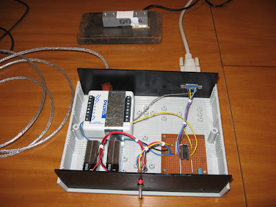 I was able to easily measure loads as low as 20 grams on the 70Kg load-cell. Initially I had some issues with noise being picked up by the wiring, and was able to reduce that about 10 fold with appropriate shielding and grounding things. Later, on the Australian rocketry forum one of the guys suggested how to even further improve the noise margin with cabling and locating the amplifier close to the load cell in a metal box. So the next step is to try that. Luckily I have all the necessary components, but will buy a new diecast aluminium box tomorrow and fit the amplifier in that.
The more accurate the setup is, the more accurately we can determine what effects design changes have on the rocket. With the above setup we can resolve ~0.2Newtons of thrust over the typical test range of about 30N to 150N. That range applies for our typical rockets with pressures of around 120psi with nozzles under 10mm. The same setup will also be used for full bore tests of up to around 600N.
I'm pretty happy with the sensitivity of the setup as is and would be great for most of the tests, but hopefully with the improved cabling and shielding we should be able to achieve higher resolution. I'll post an update when we test that.
I mounted the load cell for the time being to a big chunk of steel which will be eventually mounted on the test stand.
_________________________________________________
Saturday, August 16, 2008
New test stand work
We have been working on a side project for the past couple of weeks. We are keen to build a new thrust measuring test stand for testing design changes, but doing it the old way of recording a kitchen scale on video and then manually transferring the data into a spreadsheet just wasn't going to cut it for accuracy, and especially for making multiple runs.
We are doing it properly this time with an electronic data logger and a load cell hooked up to the laptop. The main problem with trying to do it the proper way is the higher cost involved as the equipment typically isn't your regular mass produced consumer electronics. The guys on the Australian Rocketry forum were a great help in recommending which equipment to use, things to look out for, and generally how to set it up. The data-logger we chose was from DATAQ. They have a number of different loggers with different capabilities at a very reasonable prices. I was very impressed with the delivery time from the time that I ordered. I placed my order just before lunch time on Thursday with the Australian distributor, and the package from Melbourne was waiting for me on Friday when I got home from work.
The load cells also tend to be quite expensive - easily upwards of $150-200+. We had been researching a lot of different companies and finally found a new 70kg load cell from a Chinese manufacturer whose cost and delivery were far cheaper than local distributors. It is still likely to be about 10 days before it arrives. I don't know what the quality is like yet, but I believe it should be great for our purposes.
The data-logger and load cell aren't enough though, and we also need a load cell amplifier as the datalogger only reads in the -10V to 10V range. The load cell only produces miliVolts over the entire deflection range which is too low for the datalogger to get enough resolution. The amplifier basically converts these small voltage changes to a voltage range usable by the logger. It also provides the necessary excitation voltage for the load cell. Again you can buy these off-the-shelf but you will pay upwards of $100+. Being on a limited budget, we decided to build our own load cell amplifier instead, which is based on an instrument amplifier IC. The circuit is relatively straight forward and these IC's are designed for exactly this task. The IC has been ordered and is on its way from the US.
I'll publish the full details of the entire setup and suppliers when it's calibrated and working properly.
The data logger came with free "lite" software for capturing and viewing the data. However, being free there are some limitations in terms of exporting the data and maximum allowed sample rate. The max sample rate is 240Hz which is more than ample for us. The full software with higher allowed sample rates is another $200. You can also buy a $99 software add-on that lets you save the captured data into Excel friendly format. (doh)
The free software, however, does record the data into their own proprietary binary file format. I recorded a number of waveforms today, and looked at the data in a hex editor. I noticed that it was not encrypted, so it was relatively easy to reverse-engineer its format and write a small program that allows me convert their format into a text .csv file format that is directly readable by Excel. (saved $99 there :) )
The entire thrust measuring test stand + software should cost us under $300 when finished.
_____________________________________________
Sunday, August 10, 2008
Baryon II and Variable Nozzle
We have finished doing the flight log update for the last launch day at Doonside. The primary goal for us was to test the Mk2 staging mechanism with a bigger booster and sustainer.

Details of the new booster and sustainer are also included in the update.
http://www.AirCommandRockets.com/day65.htm
We have also been working on a technique to expel extra foam from the rocket in flight and came across a way to make a simple variable diameter nozzle. The details of the concept and a video of how it works is included in the above update.

There is lots of testing that needs to be done on the nozzle, and different materials to try so it looks like we might need to set up our old test stand again.
___________________________________________________
Friday, August 08, 2008
Thermal Testing
We have finished writing up results of the initial thermal tests. We will be adding to this post as we do further testing over the coming months.
http://www.AirCommandRockets.com/day64.htm
I am in the process of completing the flight log update from Doonside last week. Hopefull that will get finished in the next few days.
___________________________________________
http://www.AirCommandRockets.com/day64.htm
I am in the process of completing the flight log update from Doonside last week. Hopefull that will get finished in the next few days.
___________________________________________
Sunday, August 03, 2008
Mk2 Stager with bigger booster and sustainer
This weekend we flew the Mk2. Stager with a bigger booster and a bigger sustainer to see how it performs under greater loads and higher pressure. The Baryon II booster has a 7.2L capacity, 15mm nozzle and launches with 2.8L of water. The 3.35L Tachyon V sustainer uses a 9mm nozzle and 1300ml of water/foam mix. We flew both at 120psi.

It was a good flight, but the high wind conditions on the day caused the rocket to fly in an arc rather than straight up and as a result did not reach the expected altitude. Staging happened as expected and both parachutes on the booster and sustainer opened as expected.

We are currently putting together a flight log update, although it will be perhaps a week before it is posted, as we are also in the process of completing the write-up of the thermal experiments we did last week. There wasn't enough time to post the thermal results last week as most of our spare time was taken up building the new booster and sustainer. Sometimes you have to find the balance between sitting at the computer typing and actually building hardware.
_____________________________________________________
Monday, July 28, 2008
Testing, testing and more testing
With the NSWRA launch day being postponed this weekend due to unfavorable weather conditions, we spent more time in the workshop testing all sorts of things and building a new two stage rocket that will use the Mk2 Stager.
First we pressure tested the new 3.35L sustainer to 120psi. It is using a new bottle we have not used before so we were curious to see how well it would hold up. Then we pressure tested the reinforced FTC to 180 psi. 180 psi will be the first launch pressure of this rocket. This is the actual FTC pressure vessel we will be using for our first FTC flights. The nozzle and end-cap are already attached and the entire length of the FTC has a single wrap of glass strapping tape.
After some recent great discussions on the Yahoo water rocket forum, about thermal properties of bottles, we spent some time doing thermal tests on how warm the air gets inside a rocket during pressurisation. This is important as high temperatures can weaken a bottle. The glass transition temperature for PET depends on a number of factors but can be as low as 69 degrees C.
Wikipedia lists this temperature as 75C.
"The glass transition temperature, Tg, is the temperature at which an amorphous solid, such as glass or a polymer, becomes brittle on cooling, or soft on heating. "
We are in the process of collating the information and we will try to publish it sometime this week.
___________________________________________
Tuesday, July 22, 2008
Repairs and painting
After the CATO of the reinforced rocket (Tachyon IV) at Doonside, I have rebuilt a new reinforced bottle and pressure tested the entire rocket last night to 170psi. There were no visible stress marks on it so should be good to go for this Saturday.
I am also replacing the fin section on this rocket with 3mm plywood fins directly glued to the bottle. I coated the fins with 5 minute epoxy to add a little strength and water proofing. They will be sanded and painted tonight.
At the last Doonside launch event a couple of the members suggested trying vinyl paint for the rockets. I bought some white vinyl and plastic spray paint at SuperCheap Autos, but at $15 a can that is not all that cheap. I tried the paint on a PET bottle a couple of days ago. I lightly sanded half of the bottle with very fine sand paper and left the other part untouched. After a few goes I realised that you have to spray in multiple thin coats to get good coverage without runs. The paint dried within minutes.
The paint is a little flexible so bending and squeezing the bottle had no effect on it flaking off, like we have had with other paints. The paint on the unsanded side, however, did come off very easily when scratched with a finger nail. It was a different matter on the sanded side though. The paint held very well even when scratched. I'm keen to see how well it holds up in the sun with heat and UV.
__________________________________________
Wednesday, July 16, 2008
Mk2. Staging Mechanism Details
We have posted the launch report on our website from the latest Mk2 Stager test flights. We have also included the full details of how the staging mechanism works.
The launch report is available here:
http://www.AirCommandRockets.com/day63.htm
The stager details are available here:
http://www.AirCommandRockets.com/howitworks_2.htm

___________________________________________________
The launch report is available here:
http://www.AirCommandRockets.com/day63.htm
The stager details are available here:
http://www.AirCommandRockets.com/howitworks_2.htm

___________________________________________________
Monday, July 14, 2008
Mk2. Stager Test flights
On Sunday afternoon we finally made it to the local park to test fly the Mk2 Stager, with a small booster and sustainer.
It was a good day of test flights. The first launch was good with good staging. We had a failure on the second launch with no release, but no damage was done to the staging mechanism. We made a couple of minor adjustments and then the final two flights of the day went well again. We had to leave the oval after flight #4 as it was getting too dark to shoot good video.
From simulations and the observed flight times which were relatively close to the simulated predictions the sustainer reached over the 100m (330') mark. Not bad for a little 600ml bottle with 200ml of water at 110psi.
 This is a couple of frames taken from ground video of the staging taking place. The sustainer arced over a little probably because its stability is marginal mostly due to its short length. Seen here staging is happening around the 10-15m mark.
We will post the full results of the test launches in the next few days with photos and video. Soon after that we will also do the full write up of the mechanism itself.
The next test flights of stager will likely be on a medium sized booster and a bigger sustainer. We haven't settled on the configuration yet as we were waiting to see how these tests would go. The bigger booster and sustainer will have to be flown at Doonside.
_________________________________________
Friday, July 11, 2008
Drop Away Boosters Explained
This week we've updated the main site with the theory and an explanation of how the drop away boosters work on the Polaron rocket.
http://www.AirCommandRockets.com/howitworks_1.htm

Other than that only small amount of work has been done on actual hardware due to other commitments. The weather looks a little windy for this weekend, but hopefully it will settle down on launch day.
_________________________________________
http://www.AirCommandRockets.com/howitworks_1.htm

Other than that only small amount of work has been done on actual hardware due to other commitments. The weather looks a little windy for this weekend, but hopefully it will settle down on launch day.
_________________________________________
Monday, July 07, 2008
Booster and sustainer work for stager test
The booster is now complete for the flight test of the Mk2 stager. The sustainer needs a little more tape, and a coat of paint on the fins and it too is ready to go.

The booster is only a 2.1L spliced pair, and the sustainer is only 600mL. We built both of them small so we could test the stager at the local park. For this test we weren't all too concerned with aerodynamic efficiency. The booster uses the same parachute deployment technique that the drop away boosters use on the Polaron rocket. The parachute is behind a flap held by a wire. The other end of the wire is attached to the sustainer and as soon as the sustainer is released, it pulls the wire and deploys the parachute on the booster.
The sustainer does not have a recovery system. It just has a soft nosecone to protect it (somewhat) on landing.
We don't expect this combination to go very high, and we still need to run simulations to see what to expect. If the weather is good this weekend we will launch it.
_________________________________________
Wednesday, July 02, 2008
15mm Nozzles
We had a good weekend launching rockets despite a couple of CATOs. We launched the Axion rocket with a 15mm nozzle and a long launch tube which gives the rocket a nice kick on take-off.
The full update is available here:
http://www.AirCommandRockets.com/day62.htm
The update also includes a video of some static fire tests of the Mk2 stager we have been working on. We are keen to fly it as soon as we finish the little booster and sustainer. We will be able to test it locally without having to wait until the next launch day at Doonside.
_____________________________________________
Friday, June 20, 2008
Side Deployment Construction Tutorial
Construction details of how we make our side deployment mechanisms are available here:
http://www.AirCommandRockets.com/construction_3.htm#SideDeployment
We have been using this technique on our rockets for more than a year now. But finally got around to documenting it. All the materials used are readily available and it can be adapted to things like Tomy timers and the like.

_________________________________________
Monday, June 16, 2008
First trials of new staging mechanism
Over the last few months we have been slowly working on a new staging mechanism. On Sunday we spent some time completing it and running through some initial trials. We test fired it 3 times, at 60psi, 100psi and 120psi. We did the tests just in the back yard with only bottles connected rather than real rockets. We were pretty happy with the performance after a few adjustments.

Next we are going to build a very small second stage (~600mL), and a small booster - likely to be just a spliced pair of bottles. We want it fairly small so that it does not leave the local park. We want to see how it will go in flight before it is put on a bigger rocket with a bigger booster. This staging mechanism will eventually go on the Acceleron rocket, but could be used for a third stage on the Polaron rocket as well.
A full write-up with diagrams of the internal operation will be posted on our main site once we have done the test flights and had a chance to evaluate its performance. Weighing in at 94 grams it is a bit on the heavy side for small rockets, but for bigger rockets it won't make much difference. Acceleron's V's staging pod weighed in at over 400 grams, but also included the parachute bay.
______________________________________________
Wednesday, June 11, 2008
Weekend Work
We worked on a number of different projects this weekend. We started a small production run of nosecones with integrated deployment systems using the new V1.5 flight computer. The idea is to build a number of these nosecones into our inventory so that we can simply screw in a new one should one become damaged. This will allow us to continue development on new projects without the need to spend a lot of time on repairs.
 We also fixed up the launch release mechanism on the medium launcher after a hairline crack developed in the riser air tube. We have replaced it with a shorter much sturdier pipe that can be unscrewed. We also built a couple of swappable release heads with integrated launch tubes. The release head fitted to the release mechanism (image below) is a standard 9mm nozzle. The other two release heads are 15mm nozzles one with a 26cm launch tube to go into single bottle or robinson coupled rockets and the other has a 112cm launch tube to be used with longer, Tornado coupled and FTC rockets.

We've also did some more work on the new staging mechanism, but mostly just epoxying parts together.
We've fitted the endcap and nozzle on a full length of FTC now as we really want to get this first FTC rocket test flown. It will be launched with the new long launch tube shown above. There is still quite a bit of work to do especially on the recovery system.
______________________________________________
 We also fixed up the launch release mechanism on the medium launcher after a hairline crack developed in the riser air tube. We have replaced it with a shorter much sturdier pipe that can be unscrewed. We also built a couple of swappable release heads with integrated launch tubes. The release head fitted to the release mechanism (image below) is a standard 9mm nozzle. The other two release heads are 15mm nozzles one with a 26cm launch tube to go into single bottle or robinson coupled rockets and the other has a 112cm launch tube to be used with longer, Tornado coupled and FTC rockets.
We've also did some more work on the new staging mechanism, but mostly just epoxying parts together.
We've fitted the endcap and nozzle on a full length of FTC now as we really want to get this first FTC rocket test flown. It will be launched with the new long launch tube shown above. There is still quite a bit of work to do especially on the recovery system.
______________________________________________
Wednesday, June 04, 2008
Flight Computer V1.5
The full construction details of V1.5 are now available here:
http://www.AirCommandRockets.com/flight_computer_V1_5.htm
Features include:
The update includes a short video of the operation, as well as circuit diagrams and PCB layout.
We've got 10 boards done now and are in the process of populating 5 of them with components. We'll be switching all our rockets to these over the coming weeks as we put this version through various trials.

___________________________________________
http://www.AirCommandRockets.com/flight_computer_V1_5.htm
Features include:
- Dual RC servo motor control
- 7-segment LED display indicating status information
- Built in launch detect G-switch
- External launch detect / burnout / negative-G trigger input
- Buzzer for indicating status and helping to locate lost rocket in tall bushes
- EEPROM used to store settings while power is turned off
- 15 configurable control parameters
- Altimeter/auxiliary power connector
The update includes a short video of the operation, as well as circuit diagrams and PCB layout.
We've got 10 boards done now and are in the process of populating 5 of them with components. We'll be switching all our rockets to these over the coming weeks as we put this version through various trials.

___________________________________________
Monday, June 02, 2008
Polaron VI to 637 feet
We had another great day this weekend launching rockets at the NSWRA launch meet. There was a unique opportunity to launch during a fog to see if we could get video from above it, and we managed to get a personal best altitude with our Polaron VI rocket on another flight.
Full details, photos and a highlights video of the day is available here:
http://www.AirCommandRockets.com/day61.htm


Full details, photos and a highlights video of the day is available here:
http://www.AirCommandRockets.com/day61.htm


Wednesday, May 14, 2008
Repairs and New Development
This past week we have been making repairs to the Polaron V rocket as well as doing some new development for Acceleron.
All the plastic retaining tubes have been removed from the Polaron V main stage. On inspection one other tube was cracked (other than those that were shredded) . Because of the forces involved we didn't want to take any more chances with plastic, so we replaced them with thin walled brass tubes. Although adding a little more weight, they should be up to the job. We will need to do some tests first though before giving them the all clear. We are giving the PL a week to fully cure. Other than the tube replacement the rest of the rocket and boosters are ready to go. The plan is to launch the rocket at the next NSWRA launch event in a couple of weeks time.
Acceleron has been mostly repaired with the exception of the staging mechanism. Over the last month or so we have been working on yet another staging mechanism, and with the repairs needing to be done for Acceleron's staging mechanism we decided to complete it and put on Acceleron IV. We still have a long way to go with it, and need to do more testing, but so far the development has been going well. I will post full details once it has flown. It is a lot more compact and lighter than what was used on Acceleron previously.
Since we are rebuilding the staging mechanism it was a good opportunity to upgrade the Tachyon sustainer. We are building a completely new sustainer that has ~30% more capacity, more streamlined shape and new parachute deployment based on V1.5 of the flight computer. The fin section now integrates a ring fin with 4 smaller conventional fins. The ring fin struts are made from 6mm carbon fiber tubing and act as supports for the sustainer during the boost phase. The sustainer also carries both the altimeter and camera. As of last night the pressure chamber (3.35L capacity) is now complete, as are the 4 fins.
____________________________________________________
Tuesday, May 06, 2008
Good Day / Bad Day
The details from the last launch day have been uploaded to the main site:
http://www.AirCommandRockets.com/day59.htm
Although it was a less than optimal day in terms of requiring repairs, we had a great day launching with other NSWRA members and even reached our highest directly measured altitude. With the same flight we also achieved our longest duration flight.
Repairs are already underway, and we are looking forward to the next launch day to fly Polaron V again.
 We have also added a size comparison rocket gallery of our rockets built to date. You will need to have a flash player installed in your browser. Just roll the mouse left or right over the screen to scroll.
_______________________________________
Monday, April 28, 2008
Our First FTC pressure tests
We did our first T-8 FTC pressure test this weekend. Over the last two weeks we made up a 15 mm nozzle and an end cap that fit exactly inside the FTC. The nozzle is a standard 15mm Gardena style nozzle but one that comes with a threaded section. We made an adapter that allowed us to screw in the nozzle. The adapter has two grooves in it, one to hold an O-ring that seals against the FTC and the other allows the tube to be shrunk to stop the nozzle from flying out. We wrap some wire over the shrunk groove to keep the nozzle in place.
The inspiration for this retention setup came from Urie's water rockets. They have good photos of the nozzle and a good description of the technique.
When we tried to shrink the nozzle end by heating it with a blow torch, we forgot the fact that other parts of the FTC were also going to get heated. *doh* We ended up buckling a part of the FTC near the nozzle. Since this was only going to be a pressure test we didn't really care. Mind you when we were sealing up the end cap we filled the FTC with water, and that went a lot better.
The burst pressure was 190 psi (13.1 bar). The nozzle and end cap stayed in place so we were happy about that. This FTC is really thin walled compared to another length of FTC we got from Damo quite a few months back. The next test will be to wrap some of the glass strapping tape around it and see how much more *crossed fingers* it will hold.
 You can see on the left edge where the FTC split.
__________________________________________________
Saturday, April 26, 2008
Flight Computer Q & A
- Why do you need a flight computer, wouldn’t a Tomy Timer do the same thing?
When you only need a one-shot timer, we always recommend a Tomy Timer as they are inexpensive, you can get them anywhere, there is no need for batteries, very simple operation and light-weight. They are also a proven design.
We wanted to be able to do more than just deploy a single parachute. A PIC-based micro-controller is an easy way to gain more functionality. Electronic timing is typically more accurate and repeatable compared to mechanical systems. You can also set very short timing delays for things like staging, something difficult to do with a Tomy Timer. There are elaborate mechanical systems that have been built that require no electronics that achieve the same thing.
A flight computer can have: data logging capability, can control multiple actuators and have in-flight data processing and signal conditioning capability. If you wanted to experiment with active stability, or gather engineering data, it is difficult to do with a Tomy timer. - Isn’t it much heavier than a Tomy Timer?
With our current design when you add the battery, servo and the flight computer it is perhaps 4 or 5 times heavier than a Tomy Timer. However, we use the battery for both the flight computer and the altimeter, so we save weight that way. The same battery could power the camera as well so you could save weight even further. We haven’t shared the power between the cameras and the flight computer yet.
If you were to use a small lightweight battery such as the 4LR44, a 4.5g micro servo and surface mount components on a small PCB it could weight about double that of a Tomy imer.
This weight difference translates to perhaps 10-20 feet altitude loss on small rockets and negligible on larger rockets.
- Why do you call it a “flight computer” and not a “timer”?
The terminology distinction is purely internal to our team. That way we differentiate between our simple electronic “timers” usually based around a 555 or 556 timer and the PIC based ones that have software running on them. Once the flight computer starts processing real-time flight data, the distinction will be more obvious. - Does it do more than timing?
The published versions of the flight computers mostly do just timing. Although through software they also drive the LED display, do switch de-bouncing and generate the correct PWM signals for the RC servo motors. - Are you looking at adding more functionality?
We have plans on our roadmap to add more functionality, but we are taking it one step at a time, experimenting with what actually works in the field what doesn’t. Take for example the various G-switch designs we’ve been testing. This involves multiple flights which takes time. - Does your current flight computer control your camera and altimeter?
The published ones and flown to date have not. The altimeter is powered from the same power source as the flight computer. The Z-log altimeter can be set up to start recording 10 seconds after power-on which means when we turn on the computer, power is also supplied to the altimeter and it starts recording. But there is no direct control between the altimeter and flight computer.
The V1.5 design has a free port left open to allow the altimeter to be connected to the flight computer through a serial connection. The Z-log altimeter outputs altimeter data continuously over its serial port. However, even V1.5 will not initially have it connected.
The plan is to feed this altimeter data to the flight computer and it will be able to monitor the altitude and deploy parachutes at preset altitudes or when altitude starts decreasing after apogee. The flight computer will always use the timer capability for backup should something go wrong with the altimeter. At the moment we are working to make the timing as reliable and usable as possible before adding more complex functionality.
It was always our intention to wire the old cameras to the flight computer so that they could be turned on by the computer just before launch since they only had 30 seconds of record time. However, ever since we bought the new FlyCamOne 2 video cameras with their 30 minute record time, the flight computer/camera integration took lower priority. We start the camera separately before we pressurize the rocket. - Do you have designs that you are keeping secret?
No. We have no reason to. We only publish the designs once we have flown them a number of times. We like to verify the designs for ourselves before making them public, as it is much easier to fix things before publishing than having to make retractions or corrections later. We find it very useful in making the designs public as other rocketeers help suggested ways of improving them.
We have already been contacted by 2 rocketeers that have built the flight computers based on our published designs, so we want to make sure we have confidence in the design before they are made public. - Isn’t it expensive?
Not really. The PIC controller costs AUD$2.84, the handful of discreet components around $10, the batteries are about $3 and the cheap 9g RC servos we get for around $6 each. This means with a PCB the whole electronics ends up costing in the order of ~$25. That is about 1/4 of the price of the camera and about 1/5th the cost of the altimeter.
Of the ones we have crashed we have been able to reuse most of the parts. Really the only things that do brake are the PCBs, the old G-switches and servos. We have now learned to protect the servos better and have had 2 survive direct impacts since the change. - Will they be available for sale?
There are currently no plans to sell them in any great numbers as there really isn’t a market for them. Most water rocketeers prefer to build rockets out of inexpensive components. Personally I’d rather be flying rockets than handling order paperwork, chasing payments, etc. etc. We will likely offer 5 of the V1.5 for sale privately at cost price. (Contact us if you are interested - see contact page on our main site) The others we will continue to use for our experiments. - How reliable are they?
So far we are having relatively good success with deploying parachutes and staging 2-stage rockets with them. All together there have been 68 flights with on-board flight computers, of which 5 failed to deploy and 2 successful deploys but tangled parachutes. This means as part of an integrated recovery system they are about 90% reliable.
- What will be in the next version?
V1.5 of the flight computer is the next iteration we are working on. This version has dual servo capability like V1.4, a loud buzzer for status feedback and helping to locate the rocket lost in tall grass or bushes. One of the new capabilities is that all the timing parameters are configurable in the field and stored in the on-board EEPROM to retain them after power is turned off. There are 15 parameters that are configurable from parachute/staging delays, to multiple servo positions, to the lost rocket sound alarm delays. We are having 9 more PCBs manufactured for this particular design as it makes it more compact and lighter. 

- Future plans?
Eventually we would like to miniaturize it and use all surface mount components and a much smaller PCB. The final weight and size should be similar to the altimeter (~10grams), although realistically this is at least a year or two away.
Adding logging capability will also be a priority in the upcoming months. We have ideas for air speed sensors that could be used to detect apogee, but have no idea how well they will work or what the data will look like. The idea is to use the normal timing for recovery, and the logging capability to capture data over multiple flights. We will do this for each type of sensor so that we can see what processing will be needed before it can be used effectively for apogee detection.
None of these plans for the flight computer are set in stone and are likely to change along the way. We only work on these during spare time and as a result the development is drawn out.
There have been many people who have flown flight computers on water rockets over the years, many of them a lot more advanced and using accelerometers, logging capability, running science experiments etc. The oldest documented reference I have found is back from March 2000.
Updated:
The following quote reproduced here in full is taken from a long exchange from the WRA2 forum and is included here because apparently we did not credit Bill with the invention of a water rocket flight computer and that we "stole" the idea from him. (See previous paragraph) In his own words:
Team Seneca Post subject: Posted: Tue Apr 15, 2008 12:13 pm
WRA2 Member
Joined: Sun Dec 31, 2006 4:40 pm
Posts: 97
Location: Seneca, N.Y.
It's not hostility. It's just that I never knew you guys would be so impressed with an electronic timer with a fancy name. I've put real computers on my rockets since the summer of 2005. A computer that does something too, not just a timer. I use an accelerometer to measure the flight and deploy. Back then I also used it to send signals to a small camera to take a snapshot at apogee. I'm the first one to put a computer on a water rocket and it was a real computer, not a tomy timer made from silicon.
_________________
Bill W.
Team Seneca
Wednesday, April 23, 2008
Polaron V Preview
Almost completed Polaron V. The main stage is close to 11L and uses a 7mm nozzle and jet foaming to produce a long a sustained thrust curve. The boosters are ~3.35L each and use a 13mm nozzle and normal water to get the main stage up to speed.

 (Click on the images to enlarge)
The lower photo shows the detail of where the parachutes are stored on the boosters. It is difficult to see the clear strap holding them in place. A wire connected to the main stage releases the strap and the parachutes can fall out. In theory anyway. We are hoping things don't get tangled on release as there will be three wires hanging from the rocket, parachutes popping left right and center and the clear straps are spring loaded so they will also be in amongst the action.
____________________________________________
Quick update
We've been progressing this week with the Polaron IV upgrade. The booster parachute deployment mechanisms are now finished on all three boosters.
I made an extra reinforced bottle for the main stage, but after gluing and heat shrinking I noticed that the coupling was sitting at a bit of an angle. This would have resulted in bent rocket, so I tried to straighten it, but instead of improving it, I managed to break the coupling. :( So I threw that bottle away and had to make up another one. The whole process takes about an hour to reinforce the bottle. We are waiting for the glue to cure before we do a full pressure test.
We've reserved Friday for a full pressure test of the new main stage and new boosters as well. If the weather is favourable we'd like to fly it on Saturday.
We also did some experiments this week in creating foam in a bucket by blowing air through a sintered metal filter into the bubble bath solution. The tiny holes help make foam more readily. We want to try generating foam on the pad to see how it compares with it generated in the air. The main observation was that if the air flowed too fast then the bubbles would re-combine into larger ones, but a slower rate created more smaller bubbles.
There have been some really good discussions on the Yahoo Water Rocket forum this week regarding internal temperatures. It may help to explain why we have had some unexpected failures of the bigger boosters under test. I'll cover this in more detail in the next web update.
_____________________________________________________
Wednesday, April 16, 2008
Progress Updates
 We have updated our main site with a few more details of what we've been up to in the workshop. The update also includes some great pictures from the last launch day taken by Andrew from NSWRA.
The update is here: http://www.AirCommandRockets.com/day58.htm

__________________________________________________
Monday, April 07, 2008
Tornado Couplings
This weekend we finally managed to produce a number of good Tornado couplings. Tornado couplings connect bottles neck to neck. These one's are easy to make out of gardening supplies from the local hardware store.

Some features:
We are also currently working on another staging mechanism design that will be hopefully a lot lighter than the one we have been using on our two stage rocket. Since we are still in the early stages of development, we will describe the design later, once it is more finalised. We have lots of testing and prototyping to do still.
_____________________________________________

Some features:
- They have a 15mm hole
- Weigh 13 grams
- Require no glue
- Have been tested to 130psi, but can most likely hold more.
- Require no special tools
- All plastic construction - no metal.
We are also currently working on another staging mechanism design that will be hopefully a lot lighter than the one we have been using on our two stage rocket. Since we are still in the early stages of development, we will describe the design later, once it is more finalised. We have lots of testing and prototyping to do still.
_____________________________________________
Tuesday, April 01, 2008
2 Stage flights
We had a great weekend launching our rockets at the NSWRA launch event. We flew our newly rebuilt 2 stage Acceleron IV rocket up to 525' (160m). We also flew the Polaron IV rocket with drop away boosters to 510'.
The full update with photos and highlights video is available here:
http://www.AirCommandRockets.com/day57.htm
Here is an panorama from around 500' as the rocket pitched over at apogee.
(click on the image to enlarge)
 ___________________________________
The full update with photos and highlights video is available here:
http://www.AirCommandRockets.com/day57.htm
Here is an panorama from around 500' as the rocket pitched over at apogee.
(click on the image to enlarge)
 ___________________________________
Tuesday, March 25, 2008
Acceleron IV progress
We spent this weekend working on the Acceleron IV booster getting it back into a working state for next week. We did a pressure test to make sure that everything is still fine, but we found out that the rocket was not holding pressure at all. We pretty quickly discovered that three of the Robinson couplings were missing their seals. Ooops. When we put those back in and everything checked out okay. We must have missed them during preliminary assembly.
We only pressure tested the rocket to ~100psi since the neighbours were out in their back yard, and having had this rocket fail a pressure test in the past, we didn't want to push it. We did have the video camera recording though just in case. The rocket will most likely get launched at 120psi on the day. The rocket theoretically should hold up to around 140psi operational pressure, with a burst pressure of around 180psi.
We hooked up all the electronics and and made sure the staging still worked when the pressure in the rocket dropped. We replaced the sustainer in the test with a small bottle full of water which fired as expected.
We replaced the rubber bands in the staging mechanism as keeping them stretched all this time in storage caused them to deteriorate quite badly. The same went for the wide rubber bands that held the fins on.
The booster segments are now attached with velcro straps which makes it a lot easier to service the segments.
The launcher has also had an upgrade with new longer fill tubes that allow us to use the spliced pairs of bottles on the bottom of each segment.
Some work has also been done on the sustainer. The altimeter has been moved into the space between the bottles which should help protect it. The altimeter is attached to the inter-bottle ring and having its own power supply allows us to swap it between rockets. We still have to re-attach the fins to the sustainer and also mount the new FlyCamOne2 camera to the payload section.
If we get time this week we also want to finish building a reinforced rocket that should be capable of around 180-200psi. It is only a two 1.25L Robinson coupled rocket but we are including the baffle we made a few months back to prevent the blow through effect with this rocket. The higher pressure would only make it worse.
We also made a couple of rocket carriers that help us transport and protect the rockets. They also help prevent the rockets from sagging in warm conditions.
__________________________________________________________
Subscribe to:
Posts (Atom)